ESP8266 Tutorials - AT Command


Serial Tool Setup


 Basic Commands

 AT
  • Command : AT+RST
  • Return response = OK
AT+RST (Reset the module)
  • Command : AT+RST
  • Return response = OK
AT+GMR (View version info)
  • Command : AT+GMR
  • Return response = Versions, OK
AT+GSLP (Enter deep sleep mode for time milliseconds)
  • Command : AT+GSLP= time
  • Return response = OK
ATE
  • Commands
    •  ATE0 - Disable echo (Doesn’t send back received command)
    • ATE1 - Enable echo (Sends back received command before response)
  • Return response = OK

WiFi Commands

AT+CWMODE (Set wifi mode0
1
2
3

AT+CWJAP (Connect to router-AP)
  • Command : AT+CWJAP?
    • Return response =
  • Commands : AT+CWJAP="ssid","password"
    • Return response = OK
AT+CWLAP (Lists available Access Points.)
  •  Set Command : AT+CWLAP = "","",""
    • Return response = AT+CWLAP = "ecn","ssid","rssi","mac"
  • Execute Commands : AT+CWJAP="ssid","password"
    • Return response = OK
AT+CWQAP (Disconnect ESP8266 from the AP is currently connected)
  • Commands : AT+CWQAP
  • Return response = OK
AT+CWSAP(configuration of softAP mode)
  •  Query
    • Command : AT+CWSAP?
    • Return response = OK
  •  Set
    • Command : AT+CWSAP=ssid,pwd,ch,ecn
    • Return response = OK
AT+CWLIF
AT+CWDHCP
AT+CIPSTAMAC
AT+CIPPAPMAC
AT+CIPSTA
AT+CIPAP

TCP

AT+CIPSTATUS
AT+CIPSTART
AT_CIPSEND 

AT+CIPCLOSE

AT+CIFSR (Query device's IP)

AT+CIPMUX
AT+CIPSERVER
AT+CIPMODE
AT+CIPSTO
AT+CIUPDATE
+IPD
AT+CIPSTART 


 Official Espressif AT firmware


Source: https://esp8266iot.blogspot.com/2015/02/esp8266-tutorials-at-command-examples.html

ESP8266 Tutorial - How to Make ESP8266 Module Breakout Boards


ESP-14 Break Out Board

                              Easily make your own DIY breakout for ESP-14. ESP8266 common breakout board does not have a bottom breakout SMD pads. To make a new Breakout Board for ESP14 module we can use two normal breakout board. its very easy and simple. 

 Watch Video First


              I bought new ESP14 Module. But i don't have ESP-14 Module Breakout Board. In ESP14 Module in bottom have six pins SCLK, MOSI, GPIO-10, GPIO-9, MISO and CS0 pin.  So should use this pins for program to STM8 controller.  i think to use my ESP8266 common breakout board, its does not have a bottom breakout SMD pads. To make a new Breakout Board for ESP14 module we can use two normal breakout board. its very easy and simple. 

 Step-1 (Use two normal breakout board)

2 x

Step-2 (Cut one board as shown the below pic-1 and cut another board as shown pic-2)


Pic-1
Pic-2
Pic-1

 Step-3 (Solder ESP-14 board) Done!


ESP-07 Break Out Board-1


ESP-07 Break Out Board-2


Thanks Regards

Source: https://esp8266iot.blogspot.com/2017/02/esp8266-tutorial-how-make-ESP14-board.html

ESP8266 Tutorial - Various Ai-Thinker's ESP8266 Modules

The AI-Thinker modules are succinctly labeled ESP-01 through ESP-13. NodeMCU boards extend upon the AI-Thinker modules. Olimex, Adafruit, Sparkfun, WeMos, ESPert (ESPresso) all make various modules as well.


Vender :  AI-thinger


1.ESP-01

  • PCB Antenna, through matching, distance do open 400 Meters, easy to use

2. ESP-02 

  • SMD package for the commit limit, the antenna can be used IPX End leading housing.

3.ESP-03

  • SMD package, built-in ceramic antenna technology, all available IO Leads.

4.ESP-04

  • SMD package, customers can custom antenna types, flexible design, all available IO Leads.

5.ESP-05

  • SMD package, and only leads to serial RST Feet, small size, external antenna.

6.ESP-06

  • Bottom mount technology, all IO Mouth leads, with metal shielding shell, can be had FCCCE Certification is recommended.

7.ESP-07

  • Half-hole chip technology, all IO Leads, with metal shielding shell, can be had FCCCE Certification, external IPX Antenna, built-in ceramic antenna can also be used.

8.ESP-08

  • with ESP-07 Except that the antenna customers can define their own form.

9.ESP-09

  • Ultra-small size package, only 10 * 10 Mm, four-layer board technology ! 1M byte.

11.ESP-11

  • Chip interfaces, ceramic antenna, small volume.

12. ESP-12

  • Semi-hole patch process , all IO Leads, with metal shielding shell, passed FCCCE Certification, built PCB Onboard antenna, 4M byte Flash.

13.ESP-12E

  • On the basis of the ESP-12 leads to 6 feet and more, greatly enhanced anti-jamming capability, the main recommendation of this section!

14.ESP-13

  • The 4-layer design, semi-hole chip technology, all IO leads, with metal shielding shell, the antenna redesigned, RF performance!

15. ESP14

  • In ESP-12E prototype design, interior adds STM8S003F3P6, and by STM8S ESP8266 AT commands to control the module is a complete STM8S microcontroller can operate via WIFI STM8 microcontroller programming.
Source: https://esp8266iot.blogspot.com/2017/02/esp8266-tutorial-various-ESP8266-modules.html

Getting Started with ESP8266


Who is Espressif??


  • 2008 - Founded 
  •  2010 - First Wi-Fi chip (offers IoT/LP WiSoCs)

             Espressif Systems is a fabless semiconductor company, with headquarters in Shanghai Zhangjiang High-Tech Park, providing low power Wi-Fi and Bluetooth SoCs and wireless solutions for the Internet of Things (IoT)applications.

ESP8266

Pin Definition

Functional Description

Main Technical Specifications

Wi-Fi Features

  • Standards - FCC/CE/TELEC/SRRC
  • Protocols - 802.11 b/g/n/e/i
  • Frequency Range  -  2.4GHz - 2.5GHz (2400MHz to 2483.5MHz) 
  • Tx Power
    • 802.11 b: +20 dBm
    • 802.11 g: +17 dBm
    • 802.11 n: +14 dBm 
  • Rx Sensitivity
    • 802.11 b: -91 dbm (11 Mbps)
    • 802.11 g: -75 dbm (54 Mbps)
      • 802.11 n: -72 dbm (MCS7) 
    • Antenna - PCB Trace, External, IPEX Connector, Ceramic Chip

    Hardware

    • CPU 
      • Tensilica L106 32-bit micro controller 
      • Ultra-low-power 16-bit RSIC
      • clock speed is 80 MHz. (maximum – 160MHz)
    • Peripheral Interface 
      • GPIO (General Purpose Input/Output)          - 17 GPIOs 
      • UART (Universal Asynchronous Receiver Transmitter) – 2 UART 
        • TX, RX 
        • UART0, UART1 
      • SDIO (Secure Digital Input/Output)             - 1 SDIO 
        • CLK, DATA_0, DATA1, DATA_2, DATA_3, CMD 
        • Supported 4 bit 25MHz SDIO v1.1 and 4 bit 50 MHz SDIO v2.0 
      • SPI (Serial Peripheral Interface-CLK, MISO, MOSI, CS) - 3 SPIs 
        • One General Slave/Master SPI 
        • One Slave SDIO/SPI 
        • One General Slave/Master HSPI 
      • I2C (Inter Integrated Circuit-SCL, SDA)               -One I2C 
      • I2S - (Inter Integrated sound)WS2812 series          - One I2S 
      • IR Remote Control (IR_Tx, IR_Rx)                       - One IR 
      • ADC (Analog to digital Converter)     10 Bits         - One ADC 
      • PWM (Pulse with Modulation)                              - 4 PWM 
      • LED Light & Button
    • Operating Voltage (1.85vmin)  3.0V ~ 3.6V 
    • Operating Current Average value: 80 mA (Min require 230mA)
    • Operating Temperature Range -40°C ~ 125°C
    • Storage Temperature Range -40°C ~ 125°C
    • Package Size                   QFN32-pin (5 mm x 5 mm)

    Software

    • Wi-Fi Mode                    station/softAP/SoftAP+station
    • Security                         WPA/WPA2
    • Encryption                      WEP/TKIP/AES
    • Firmware Upgrade 
      • UART Download 
      • OTA (via network-1MB)
    • Software Development 
      • Supports Cloud Server Development /Firmware and SDK for fast on-chip programming
    • Network Protocols          IPv4, TCP/UDP/HTTP/FTP
    • User Configuration 
      • AT Instruction Set, 
      • Cloud Server, 
      •  Android/iOS App 

    Power Consumption

    Package Information

    Applications

    • Home Appliances
    • Home Automation
    • Smart Plugs and Lights
    • Mesh Network
    • Industrial Wireless Control
    • Baby Monitors
    • IP Cameras
    • Sensor Networks
    • Wearable Electronics
    • Wi-Fi Location-aware Devices
    • Security ID Tags
    • Wi-Fi Position System Beacons


    Programming Language & Method

    • AT Command
    • C++ Language (ESPressif Core, Arduino Core)
    • ESP8266 BASIC (browser based development environment)
    • JavaScript API (Mongoose OS)
    • Lua Script (NodeMCU)
    • Micro Python

    Different Kind of ESP8266 module Boards

    Different Kind of ESP8266 Programming Tools

    • AT (Any Serial Programmer)
    • C++ Language
      • Arduino IDE
      • ESPressif SDK
    • ESP8266 BASIC (browser based development environment)
    • Mongoose OS
    • Lua Script (NodeMCU)
      • LuaLoader (NodeMCU Programs)
      • ESPlorer  (NodeMCU Programs)
      • EspFlasher tool (NodeMCU)
    • Micro Python 
      •  Python [ Expressif’s Flash Download Tools (ESP8266 & ]
      • NodeMCU 


    ESP8266 BASIC


    Main Disadvantage is of ESP8266 BASIC?

        512k modules will not support all features of ESP8266 BASIC.
        To make it fit on an ESP-01 and alike the following features have been removed for 512k modu

    Features

        Browser Based debugger
        Vars page
        TFT display functions
        OLED display commands
        LCD display commands

    How to flash your chip ?

        1. Downlaod the flash tool from below Links
            https://www.esp8266basic.com/download.html
      
            Full Source code on the github
                https://github.com/esp8266/Basic/tree/NewWebSockets
        2. follow this instruction from this below link website
                https://www.esp8266basic.com/flashing-instructions.html

    Downlaod Getting started videos from below links

        ESP8266 Basic Interpreter from ESP8266basic.com         https://www.youtube.com/watch?v=ntYJ5TErJLk
      

      YouTube playlist of ESP8266 Basic

        https://www.youtube.com/playlist?list=PLeoCiKHizvH90nsLnBd_eEbzAGodfIE05

    ESP8266 Useful Books


    Websites

    ·        http://esp8266.ru/
    ·        http://www.esp8266.com/
    ·        https://nurdspace.nl/ESP8266
    ·        http://benlo.com/esp8266/
    ·        NodeMCU
    o   https://github.com/nodemcu/
    o   http://nodemcu-build.com (NodeMCU Custom Build)

    Source: https://esp8266iot.blogspot.com/2017/03/Getting-Started-With-ESP8266.html


    DSC_1987
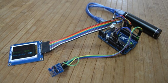
    This is my first attempt to receive data with an Arduino and the ESP8266 WiFi-Module. This program is based on the example by Seedstudio, and displays weather data on a small TFT display.

    The Modul

    esp8266_pinout_h
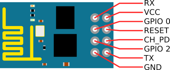
    I bought this module at Electrodragon. This Version has two LEDs, one for Power and another one which is connected to the TX-Pin. It runs at 3.3 Volt and the serial port is set to a data rate of 115200 baud. The CH_PD-Pin has to be high. After a reset, the module sends the following data:
    1
    2
    3
    4
    5
    6
    7
    8
    9
    10
    11
    12
    13
    14
    15
    16
    17
    18
    19
    AT+RST
    OK
     ets Jan  8 2013,rst cause:4, boot mode:(3,6)
    wdt reset
    load 0x40100000, len 24236, room 16
    tail 12
    chksum 0xb7
    ho 0 tail 12 room 4
    load 0x3ffe8000, len 3008, room 12
    tail 4
    chksum 0x2c
    load 0x3ffe8bc0, len 4816, room 4
    tail 12
    chksum 0x46
    csum 0x46
    ready

    Wiring

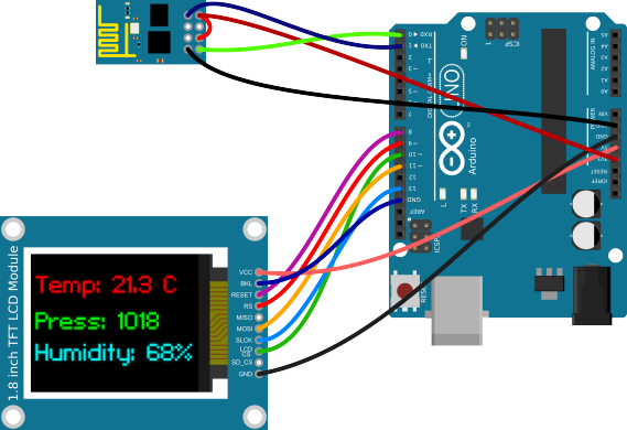
    The wiring is quite simple. The wifi-module needs just two wires for power and two for the serial interface. As a display i used a 1.8″ (45.72 mm) TFT-display that is connected via SPI.


    weather-display

    ArduinoESP8266 ModuleDisplay Module
    3.3VVCC & CH_PD
    5VVCC
    GNDGNDGND & BKL
    0 (RX)TX
    1 (TX)RX
    8RESET
    9RS
    10LCD CS
    11MOSI
    13SLCK

    The Program

    I changed the source code from Seedstudio a little bit, because at 115200 baud the 64 Byte uart-buffer from the Arduino fills up very fast. But overall the program is really simple.
    1
    2
    3
    4
    5
    6
    7
    8
    9
    10
    11
    12
    13
    14
    15
    16
    17
    18
    19
    20
    21
    22
    23
    24
    25
    26
    27
    28
    29
    30
    31
    32
    33
    34
    35
    36
    37
    38
    39
    40
    41
    42
    43
    44
    45
    46
    47
    48
    49
    50
    51
    52
    53
    54
    55
    56
    57
    58
    59
    60
    61
    62
    63
    64
    65
    66
    67
    68
    69
    70
    71
    72
    73
    74
    75
    76
    77
    78
    79
    80
    81
    82
    83
    84
    85
    86
    87
    88
    89
    90
    91
    92
    93
    94
    95
    96
    97
    98
    99
    100
    101
    102
    103
    104
    105
    106
    107
    108
    109
    110
    111
    112
    113
    114
    115
    116
    117
    118
    119
    120
    121
    122
    123
    124
    125
    126
    127
    128
    129
    130
    131
    132
    133
    134
    135
    136
    137
    138
    139
    140
    141
    142
    143
    144
    145
    146
    147
    148
    149
    150
    151
    152
    153
    #include <SoftwareSerial.h>
    #include <JsonParser.h>
    #define cs   10  // Pins for the display
    #define dc   9
    #define rst  8
    #include <Adafruit_GFX.h>    // Core graphics library
    #include <Adafruit_ST7735.h> // Hardware-specific library
    #include <SPI.h>
    Adafruit_ST7735 tft = Adafruit_ST7735(cs, dc, rst);
    using namespace ArduinoJson::Parser;
    #define SSID "<ssid>" // insert your SSID
    #define PASS "<password>" // insert your password
    #define LOCATIONID "2925533" // location id
    #define DST_IP "188.226.224.148" //api.openweathermap.org
    SoftwareSerial dbgSerial(2, 3); // RX, TX for debugging
    JsonParser<32> parser;
    void setup()
    {
      Serial.begin(115200);
      Serial.setTimeout(5000);
      dbgSerial.begin(9600); // for debuging
      dbgSerial.println("Init");
      tft.initR(INITR_BLACKTAB);
      tft.setRotation(1);
      tft.fillScreen(ST7735_BLACK);
      tft.setCursor(2, 2);
      tft.setTextColor(ST7735_WHITE);
      Serial.println("AT+RST"); // restet and test if module is redy
      delay(1000);
      if(Serial.find("ready")) {
        dbgSerial.println("WiFi - Module is ready");
        tft.println("WiFi - Module is ready");
      }else{
        dbgSerial.println("Module dosn't respond.");
        tft.println("Module dosn't respond.");
        tft.println("Please reset.");
        while(1);
      }
      delay(1000);
      // try to connect to wifi
      boolean connected=false;
      for(int i=0;i<5;i++){
        if(connectWiFi()){
          connected = true;
          tft.println("Connected to WiFi...");
          break;
        }
      }
      if (!connected){
        tft.println("Coudn't connect to WiFi.");
        while(1);
      }
      delay(5000);
      Serial.println("AT+CIPMUX=0"); // set to single connection mode
    }
    void loop()
    {
      String cmd = "AT+CIPSTART=\"TCP\",\"";
      cmd += DST_IP;
      cmd += "\",80";
      Serial.println(cmd);
      dbgSerial.println(cmd);
      if(Serial.find("Error")) return;
      cmd = "GET /data/2.5/weather?id=";
      cmd += LOCATIONID;
      cmd += " HTTP/1.0\r\nHost: api.openweathermap.org\r\n\r\n";
      Serial.print("AT+CIPSEND=");
      Serial.println(cmd.length());
      if(Serial.find(">")){
        dbgSerial.print(">");
      }else{
        Serial.println("AT+CIPCLOSE");
        dbgSerial.println("connection timeout");
        tft.fillScreen(ST7735_BLACK);
        tft.setCursor(2, 2);
        tft.setTextColor(ST7735_WHITE);
        tft.println("connection timeout");
        delay(1000);
        return;
      }
      Serial.print(cmd);
      unsigned int i = 0; //timeout counter
      int n = 1; // char counter
      char json[100]="{";
      while (!Serial.find("\"main\":{")){} // find the part we are interested in.
      while (i<60000) {
        if(Serial.available()) {
          char c = Serial.read();
          json[n]=c;
          if(c=='}') break;
          n++;
          i=0;
        }
        i++;
      }
      dbgSerial.println(json);
      JsonObject root = parser.parse(json);
      double temp = root["temp"];
      double pressure = root["pressure"];
      double humidity = root["humidity"];
      temp -= 273.15; // from kelvin to degree celsius
      tft.fillScreen(ST7735_BLACK);
      tft.setCursor(2, 25);
      tft.setTextColor(ST7735_BLUE);
      tft.setTextSize(2);
      tft.print("Temp: ");
      tft.print((int)temp);
      tft.print(".");
      tft.print((int)((temp-(int)temp)*10));
      tft.println(" C");
      tft.setCursor(2, 55);
      tft.setTextColor(ST7735_GREEN);
      tft.setTextSize(2);
      tft.print("Press: ");
      tft.print((int)pressure);
      tft.setCursor(2, 85);
      tft.setTextColor(ST7735_YELLOW);
      tft.setTextSize(2);
      tft.print("Humidity: ");
      tft.print((int)humidity);
      tft.println("%");
      dbgSerial.println(temp);
      dbgSerial.println(pressure);
      dbgSerial.println(humidity);
      dbgSerial.println("====");
      delay(600000);
    }
    boolean connectWiFi()
    {
      Serial.println("AT+CWMODE=1");
      String cmd="AT+CWJAP=\"";
      cmd+=SSID;
      cmd+="\",\"";
      cmd+=PASS;
      cmd+="\"";
      dbgSerial.println(cmd);
      Serial.println(cmd);
      delay(2000);
      if(Serial.find("OK")){
        dbgSerial.println("OK, Connected to WiFi.");
        return true;
      }else{
        dbgSerial.println("Can not connect to the WiFi.");
        return false;
      }
    }

    Conclusion

    The program is quite simple and could be extended with more features like a weather forecast. If you have any comments about the source code leave it down below. I hope i don’t have to many spelling mistakes in my first English post :)
    Update: There was a bug in the code, which was found by Jody Roth. This is now fixed.

    MARI themes

    Được tạo bởi Blogger.